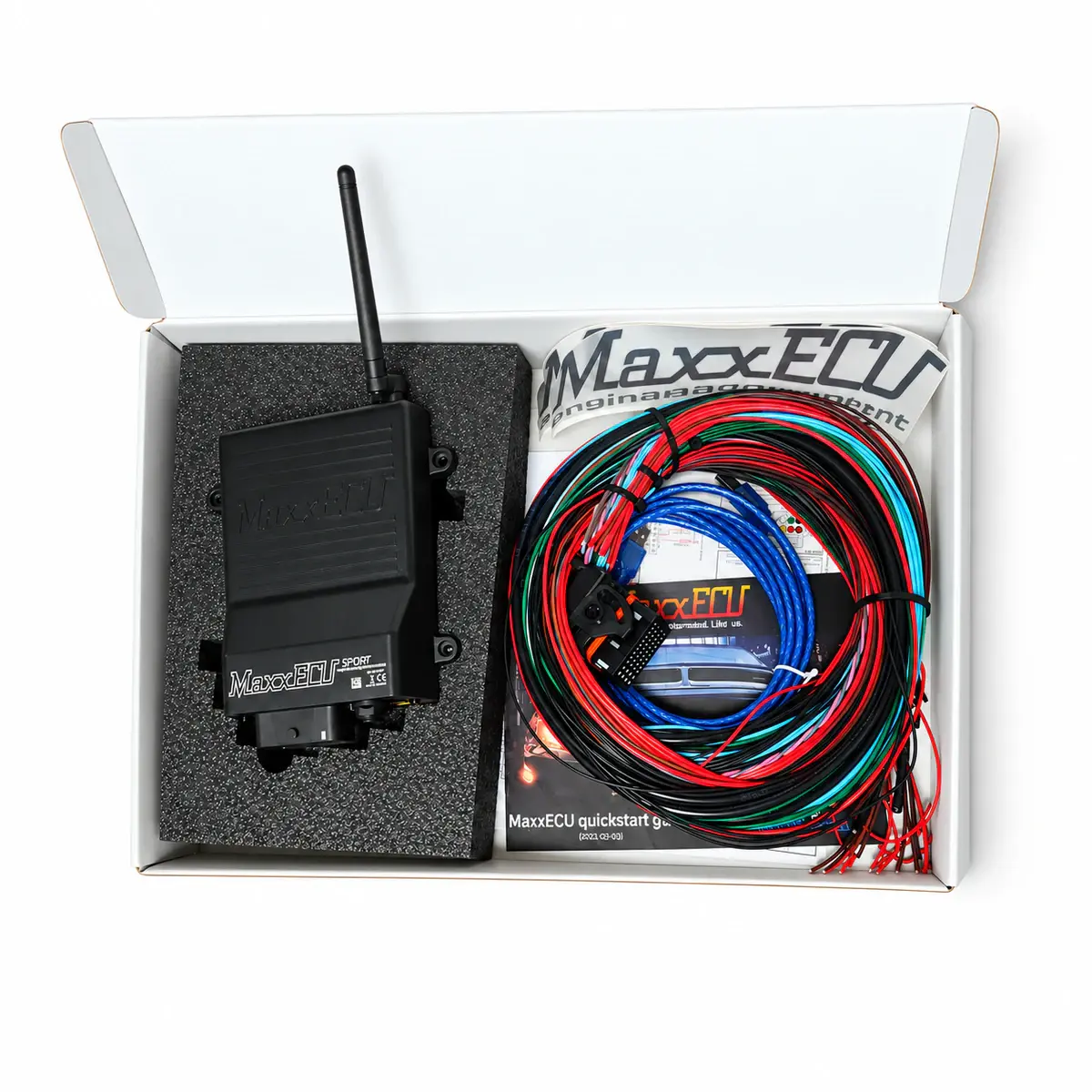
Applicability
MaxxECU SPORT REV9+; other revisions need their own wiring reference.
Hardware features
SPORT provides six peak-and-hold injector and six logic ignition outputs, wideband control and an electronic throttle driver. It has no internal knock input. Allocate motor channels separately from ordinary GPOs using the actual pinout.
I/O and driver ratings
Ignition outputs are control signals. Coils need suitable built-in igniters or a matching external module. Check injector drivers and auxiliary output electrical types separately.
| Item | Specification / revision condition |
|---|---|
| Engine configuration | 6 sequential / up to 12 wasted spark |
| Injector outputs | 6 peak-and-hold, high / low impedance |
| Ignition outputs | 6 × 5 V |
| Auxiliary outputs | 7 low-side GPO; 2 E-throttle outputs |
| Analogue inputs | 6 × 0–5 V |
| Temperature inputs | 2 extra temperature inputs |
| Trigger inputs / signal | 2 VR / Hall |
| Wideband lambda | Bosch LSU 4.2 / 4.9 |
| Electronic throttle | Built in; pedal / throttle sensors must be matched |
| Manifold pressure | 400 kPa absolute; approximately 3 bar boost at sea level |
| Data logging | 8 MB onboard; internal ≤1000 Hz, PC logging 20 Hz |
| Software / communication | MTune via USB; CAN expansion |
| CAN communication | CAN plus Bluetooth / MDash |
| Operating supply | 8–22 V DC |
| Digital inputs | 2 Hall inputs for speed sensors or switches |
| Knock inputs | No built-in knock sensor inputs |
| USB PC logging rate | 20 Hz; independent of the onboard logging maximum |
| Trigger diagnostics | Built-in trigger oscilloscope and trigger logger in MTune |
| Boost control | Open / closed loop; three stages with compensation tables |
| Injector driver rating | Peak-and-hold, up to 8 A per output; one or two matching injectors per channel |
Power, sensor ground and shielding
The diagrams distinguish engine ground, sensor ground and trigger shields. Do not connect sensor ground to chassis ground. Follow the specified shield termination and separate sensitive wiring from ignition and injector current paths.
Crank / cam and synchronization
In MTune select the actual trigger pattern, sensor type and edge. Check cranking RPM and synchronization first; an RPM reading does not establish correct cylinder phase or ignition reference. Use the trigger oscilloscope and logger to investigate tooth patterns, polarity and signal quality.
Verification before first start
With the engine stopped, check temperature, TPS, MAP and supply readings. Confirm output allocation, cylinder numbers and firing order. Test loads using the output-test procedure, verify locked ignition timing with a timing light, then make a brief first start while logging sensor states.
Reference documents
- MaxxECU — GEN1 pinout and model wiring diagrams
- Document language: English
- Document revision: GEN1
- Referenced chapters: MINI 32-pin, SPORT / RACE connector 1, RACE connector 2
- MaxxECU — GEN1 quick guide and troubleshooting
- Document language: English
- Referenced chapters: Trigger sync, output tests, first ignition and connection diagnosis