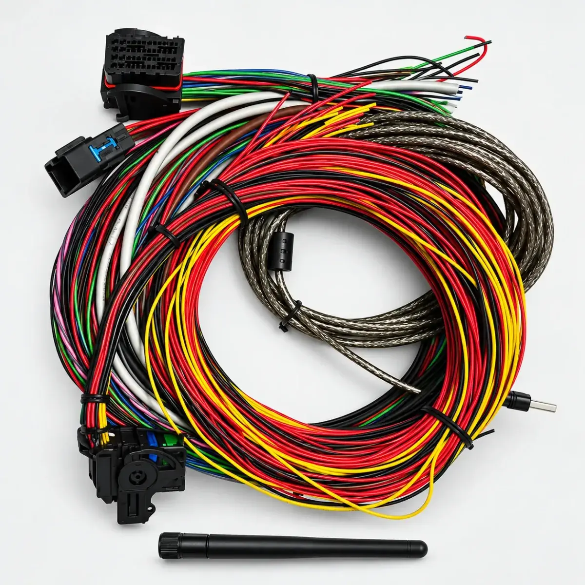
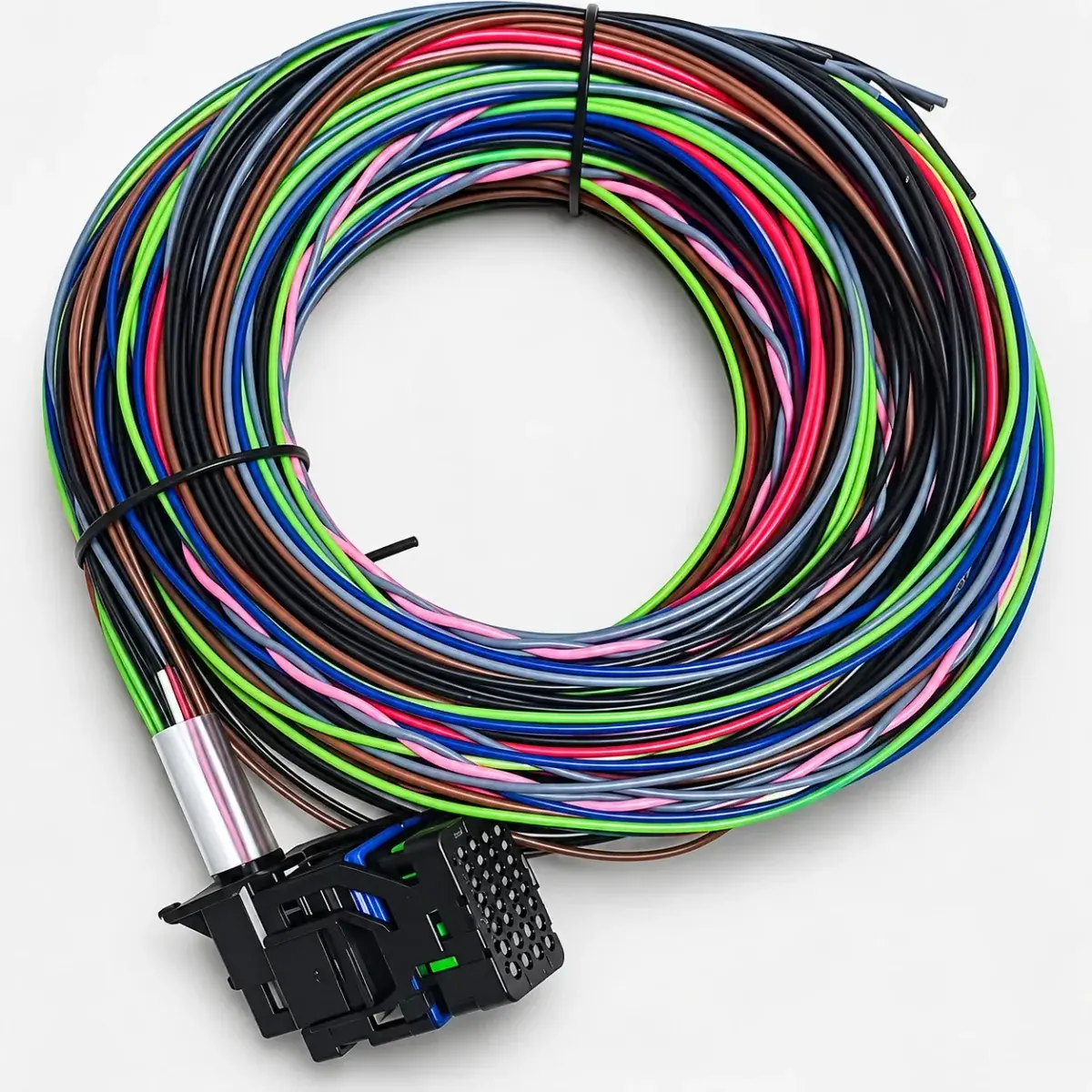
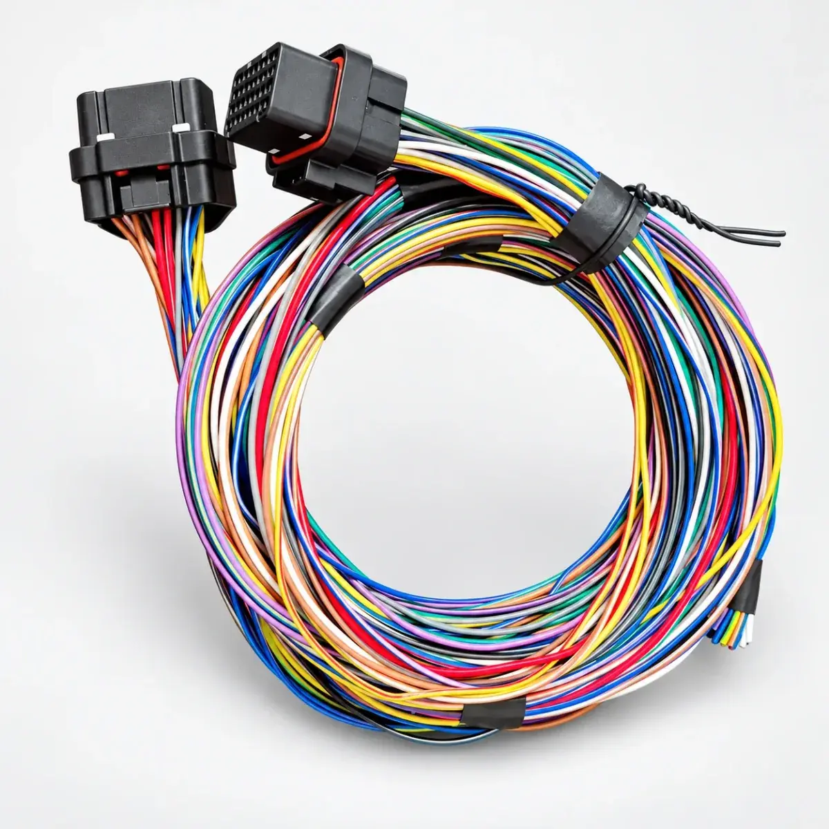
Applicability
For checking routing, pin identification, grounding and shielding during harness design.
Measure before cutting
Mark the ECU location and every connector endpoint. Measure each branch, allowing service loops and clearance from heat, moisture, vibration and moving parts. Choose sleeves and connectors for those conditions.
Label both ends
Keep a table of connector ID, cavity number, signal name and wire label. Note the drawing view: a mating-face view and a wire-entry view show the connector from opposite sides.
Use the ECU grounding diagram
Follow the matching manual for power grounds, sensor returns and shields. A similar connector does not make another model’s ground layout suitable.
Keep the finished pin map
Ask for the final pin map, connector list and agreed continuity-check record with the loom. The list should show which connections are complete and which the installer must finish.
Reference documents
- Link ECU — Getting Running