Applicability
General technical reference; always match the specific hardware and manual.
What information helps you recommend the right parts?
Provide the vehicle market and year, engine code, factory ECU label, modifications, fuel, intended use and functions to retain, together with existing accessories and the installer’s requirements. Mark any unknown details as “not yet confirmed”. Verify the exact model and hardware revision before finalizing the configuration.
How do I choose between standalone and piggyback?
A standalone takes over the engine functions assigned to it; a piggyback modifies selected signals while working with the original ECU. Review engine control requirements and retained systems together. Keeping the original ECU does not automatically guarantee compatibility with every modification.
Does the vehicle name or matching plug prove fitment?
No. Market, production date, engine, transmission, original ECU and harness revision can change the pinout and required functions. Confirm the exact application, connector view and wiring diagram. Dashboard, immobilizer, electronic throttle and transmission integration each need their own check.
Is cylinder count enough to select an ECU?
Also check injection and ignition strategy, trigger support, sensor inputs, auxiliary drivers, CAN and functions sharing the same channel. Count the required devices against the exact hardware manual. An unused pin is not necessarily an output suitable for your load.
Does installing a controller guarantee more power?
No fixed gain can be inferred from a controller model. Results depend on engine condition, airflow, fuel system, fuel, calibration and test conditions. Agree the measurement method and baseline with the tuning provider; do not treat a catalog description or a base map as a verified power result.
Can I wire a connector by colour or appearance?
Use the manufacturer’s cavity numbers, signal names and specified connector view for the exact revision. Wire colours and similar housings are insufficient. Identify whether a drawing shows the mating face or wire-entry side, and verify the pin map before applying power.
Which standard can define harness workmanship acceptance?
IPC/WHMA-A-620 provides requirements and acceptance criteria for cable and wire harness assemblies. If needed, specify the agreed revision, product class, drawings and required inspection records in the purchase specification. Citing the standard does not establish that a supplied harness or its assembler is certified.
Can sensor grounds and power grounds be combined anywhere?
Follow the exact ECU grounding diagram for sensor returns, power grounds and shields. Do not move sensor returns to an arbitrary chassis point or copy another ECU’s layout. Plan separation from ignition and other noisy wiring, and have the installer verify the finished circuit.
Can every product use the same 12 V supply and fuse?
Use the voltage range, polarity, current limits and protection specified for each device. ECU power, sensor reference supply and actuator power have different roles. Fuse rating, wire size and relay requirements must match the circuit and manufacturer instructions; there is no universal fuse value for the catalog.
Can an ignition output drive any coil directly?
Distinguish logic ignition from coil power drive. MaxxECU GEN1 requires suitable external igniters or coils with built-in power stages. Set dwell and limits for the coil; ignition pins are not general ground switches.
Will two devices communicate just because both have CAN?
No. Match the supported bus type, bitrate, message protocol, identifiers and data interpretation. ISO 11898-2 covers the high-speed CAN physical interface, not a universal application message format. A dashboard, ECU or lambda module still needs compatible protocol support or an explicitly supported configuration.
Should every CAN bus measure 60 ohms?
On a conventional high-speed CAN bus with two 120-ohm end terminators present, a suitable unpowered resistance check is typically about 60 ohms. Check topology and built-in termination first. Some MaxxECU GEN2 revisions disconnect their software-controlled resistor when unpowered, so one reading alone is not a universal pass or fail test. Never measure resistance on a live circuit.
Does a 3 bar MAP sensor mean 3 bar of boost?
Confirm whether the rating is absolute pressure. Boost above ambient equals absolute pressure minus local atmospheric pressure; 3 bar absolute is roughly 2 bar gauge at 1 bar ambient. Also match supply, pinout and the manufacturer’s voltage-to-pressure calibration. Range alone does not define calibration.
Can a Bosch LSU 4.9 connect directly to a normal analogue input?
The LSU 4.9 needs a compatible wideband controller, either inside a specifically supported ECU or in an external module. It is not a ready-made 0–5 V sensor output. Confirm sensor version, controller, heater wiring and the controller’s CAN protocol or analogue calibration; a matching connector is insufficient.
Can sensors with the same connector use the same calibration?
Not automatically. Identify the exact part number and its calibration data. Temperature sensors may need different resistance curves and pull-up settings; pressure sensors may use different voltage transfer functions. Select or enter the matching calibration and check plausible readings before starting the engine.
Where should I get manuals and tuning software?
The knowledge center contains model-specific specifications, installation notes, technical answers and software connection workflows. Search the full model and hardware revision. If you need an installation package or a version not covered here, include the ECU label and computer system in your consultation request.
Should I always install the newest tuning program?
Use the release supported by your ECU generation and firmware. Link G4+ and G4X, for example, have different software generations; legacy support may be limited. Read the matching release notes and compatibility list before connecting, and do not assume a newer family’s software supports older hardware.
What should I check if the computer cannot connect to the ECU?
Confirm ECU power, the specified cable or interface, supported operating system and architecture, and the correct software and driver. Record device-manager status and the exact error message. A USB-shaped port, adapter or historical Windows reference does not prove compatibility with your present setup.
What should I save before changing software or firmware?
Save the current calibration, ECU identity, firmware version, pin assignments and relevant logs, then read the manufacturer’s update procedure and compatibility notes. Use stable power and the specified connection. Confirm recovery and downgrade limitations beforehand; a saved map does not guarantee it can be restored to every firmware version.
Does a software disc include a licence and current OS support?
A disc or printed manual is a physical item whose edition, contents and language need confirmation. It does not establish a transferable software licence, account access, interface activation or support for a current OS. These must be checked against the manufacturer’s terms and the itemized quote.
Is a base map ready for normal driving or full load?
A base map is a starting configuration, not a validated calibration for your engine. Injector data, fuel, wiring, trigger setup, sensors and ignition settings must match the installation. Have a qualified tuning provider verify operation and calibrate the engine before relying on load-dependent performance or protection functions.
What should be verified before the first engine start?
Before starting, check power and grounds, continuity, I/O assignments, static sensors, fuel system and cranking sync. Confirm load wiring and test conditions, then verify ignition reference with a timing light.
The ECU shows RPM but the engine will not start. What information helps?
A displayed RPM value alone does not confirm correct synchronization or ignition timing. Supply the trigger configuration, trigger scope or log if supported, error counters, firing order and timing-light verification from your installer. Correct wiring and trigger faults before trying to compensate by changing fuel or ignition tables.
Which logs help diagnose a tuning or intermittent fault?
Record the calibration and firmware used, symptom, operating conditions and event time. Useful channels may include RPM, load, throttle, lambda, temperatures, supply voltage, trigger errors and protection states. Available channels, sample rates and onboard storage differ by ECU; agree the recording setup with the tuning provider.
Is a connector set the same as a completed harness?
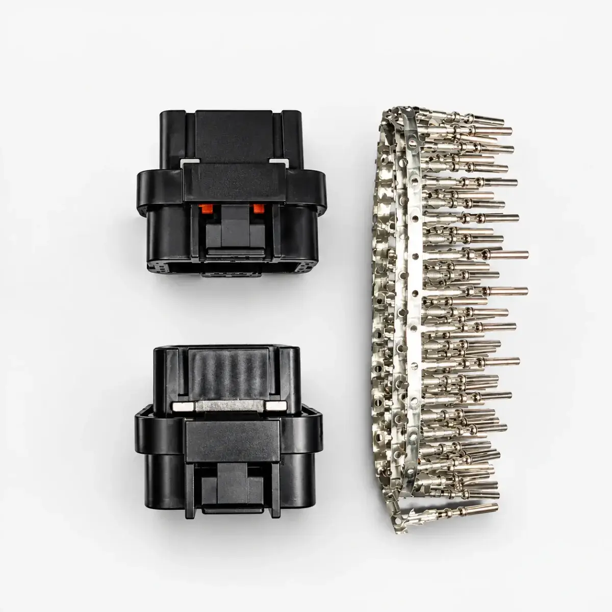
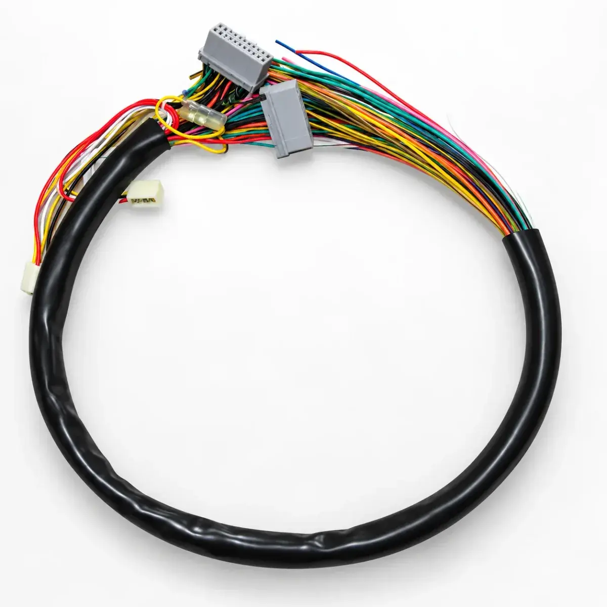
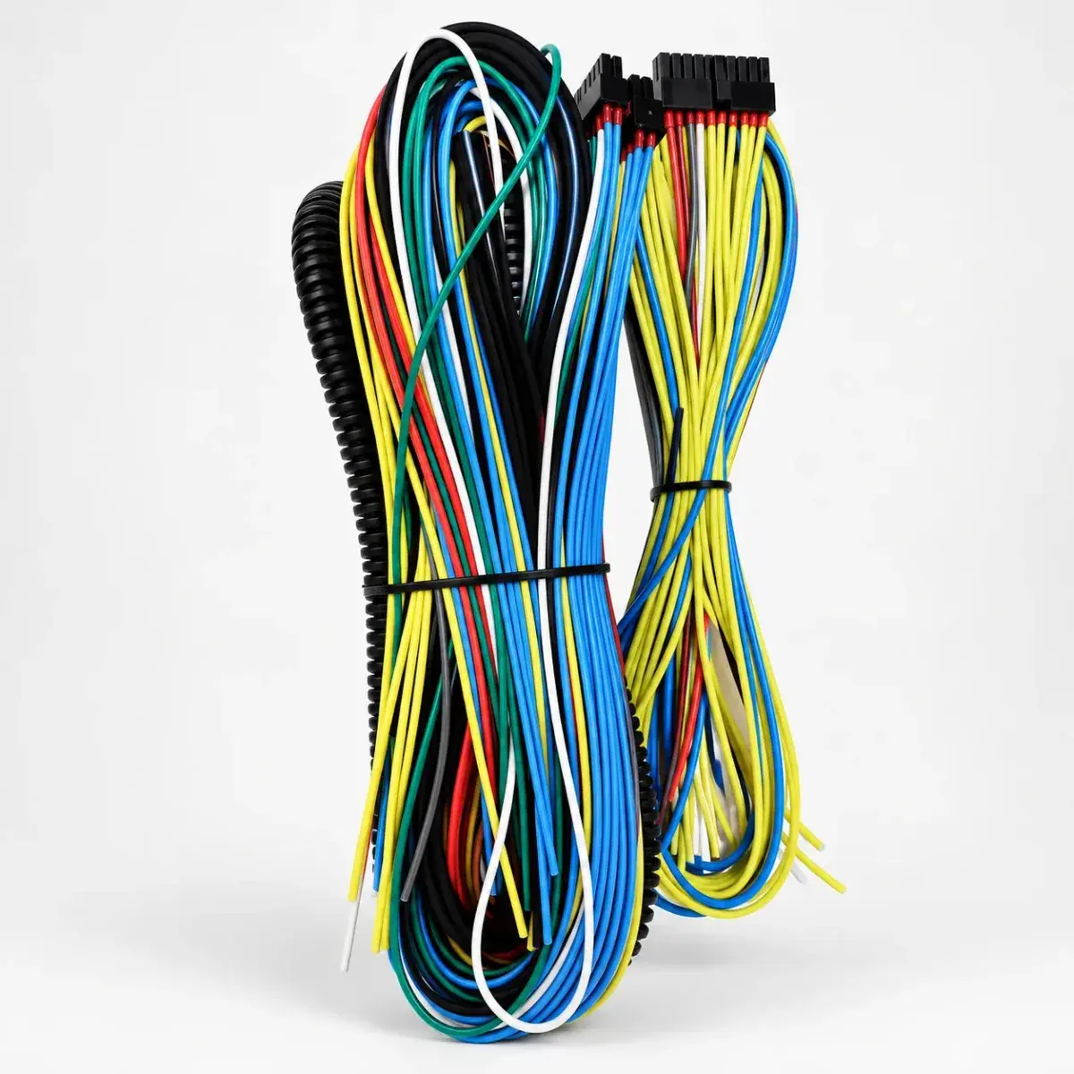
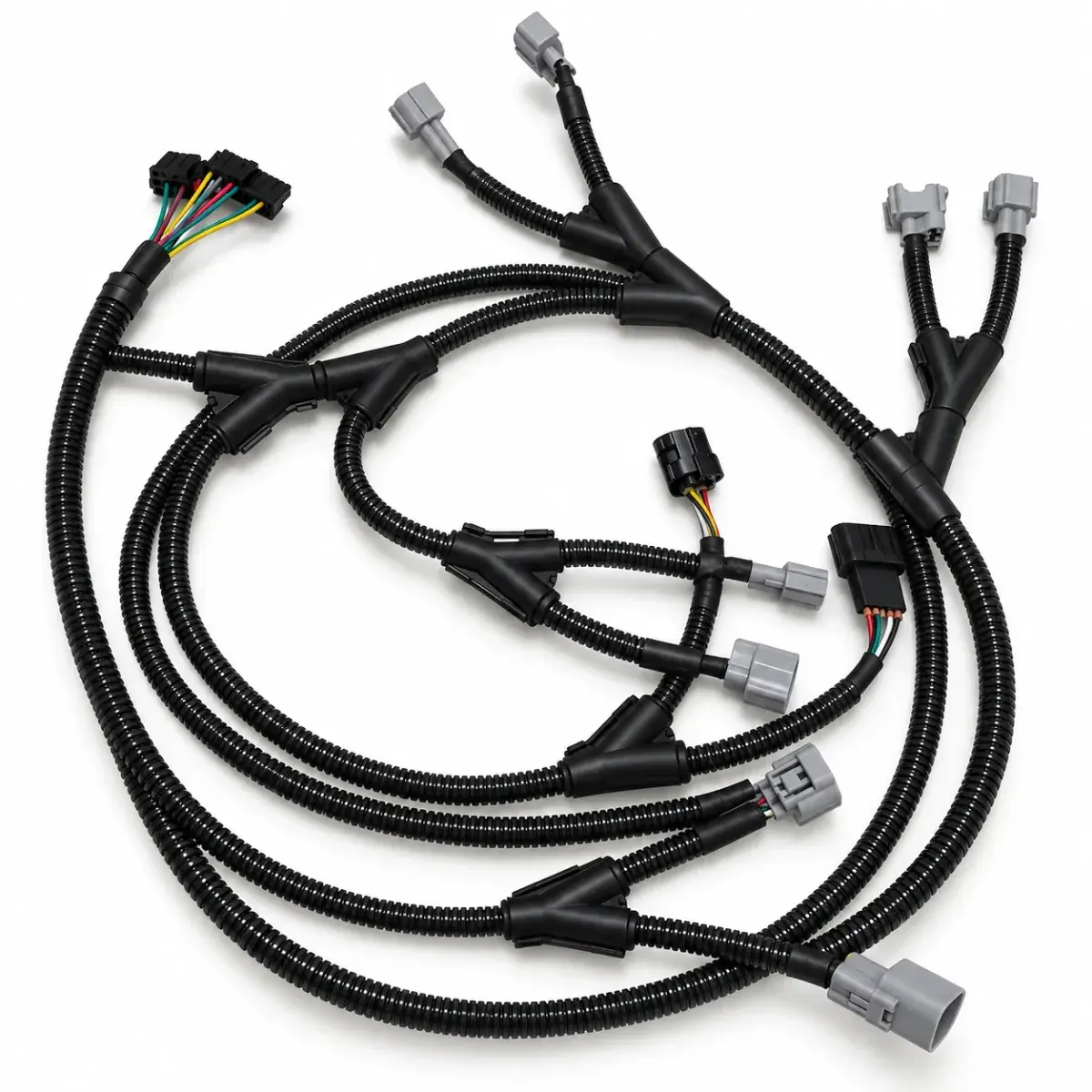
A connector set may contain loose housings, terminals and seals. A flying-lead harness leaves installation terminations to complete; a vehicle adapter has defined mating ends and application limits. Confirm pin population, lengths, branches, seals and unfinished connections rather than relying on the word harness.
What is needed before making an engine harness?
Prepare the ECU and device models, connector pinouts, mounting positions and measured branch lengths. Define the power supply, fuses, grounds, signal type and labels for each circuit. Resolve shared-pin conflicts before making the harness and retain the final wiring table.
What should be checked after wiring the harness?
Use the final pin table to check continuity, shorts, polarity and grounds circuit by circuit. Verify terminal locking, wire sizes, fuses and connector seals. Continuity alone does not verify current capacity or noise immunity; after power-up, check static sensor readings and actuator operation.
Can I replace an old controller with the same model name?
Check the complete part number, generation, hardware revision, connector pinout, firmware and supported accessories. Product families can change across generations even when names look similar. Confirm whether the existing harness, map and communication equipment remain supported before reconnecting them.
Does a sealed connector make the whole ECU waterproof?
No. ISO 20653 defines IP protection and enclosure tests for road-vehicle electrical equipment. Any claimed rating must apply to the exact enclosure and specified installation conditions. Request the product-specific rating and evidence; connector sealing alone does not establish a complete assembly rating or suitability for immersion or pressure washing.
Does an ISO 16750 reference mean a product is fully automotive-certified?
No. ISO 16750-2:2023 addresses electrical loads for road-vehicle electrical and electronic equipment; its scope excludes EMC and motorcycle or moped environmental testing. Ask for the exact test standard, edition, conditions, acceptance limits and report for the offered product. A standards reference is not a certification or evidence that testing was performed.
Reference documents
- MaxxECU — GEN1 pinout, trigger system and troubleshooting
- Document language: English
- Referenced chapters: Pin allocation, trigger synchronization and output tests
- Link — G4X and G4+ Quickstart Guides / PCLink Help
- Document language: English
- Referenced chapters: Sensors, shared I/O, CAN, logging and first start