Applicability
Controllers, harnesses and installation parts
ECU, power and protection
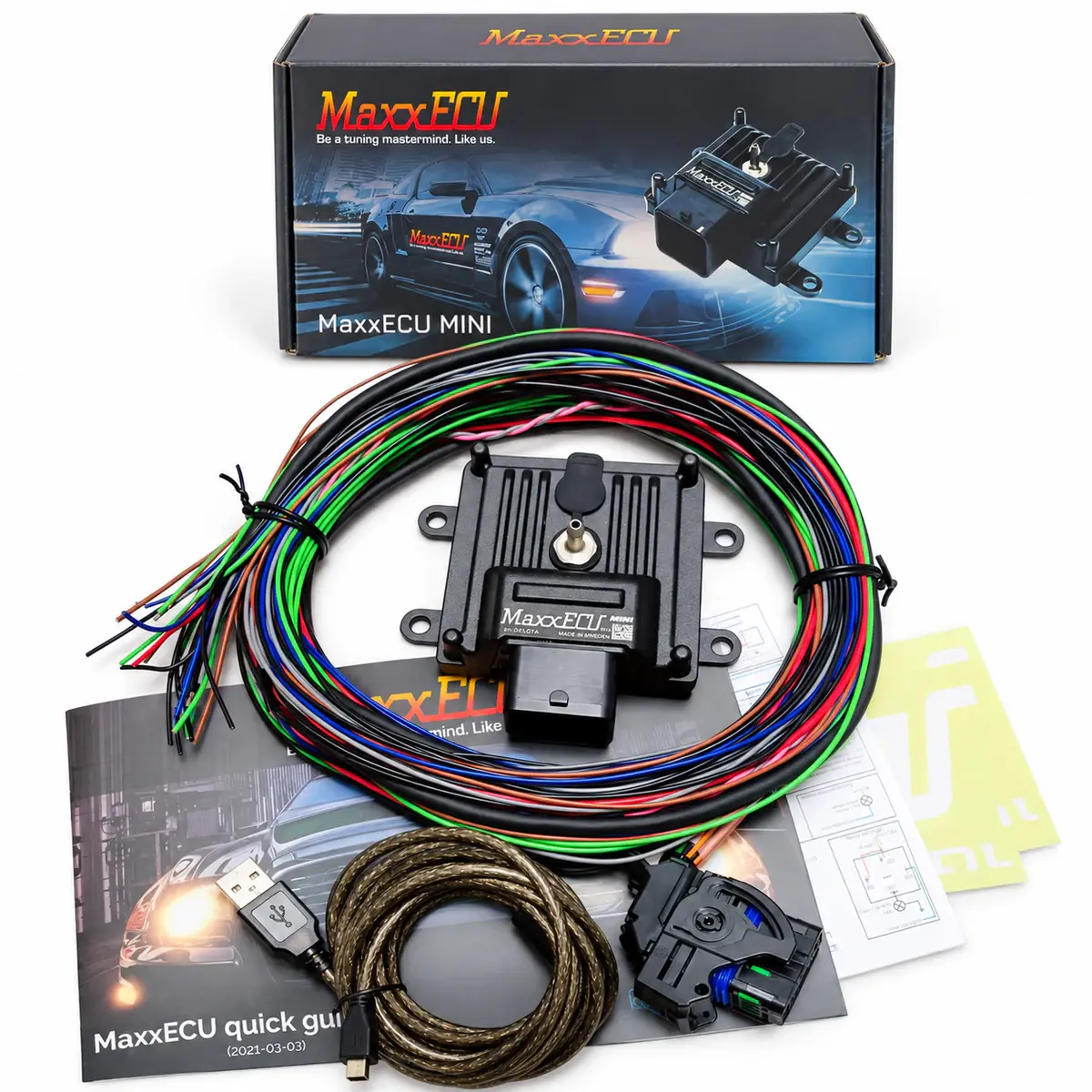
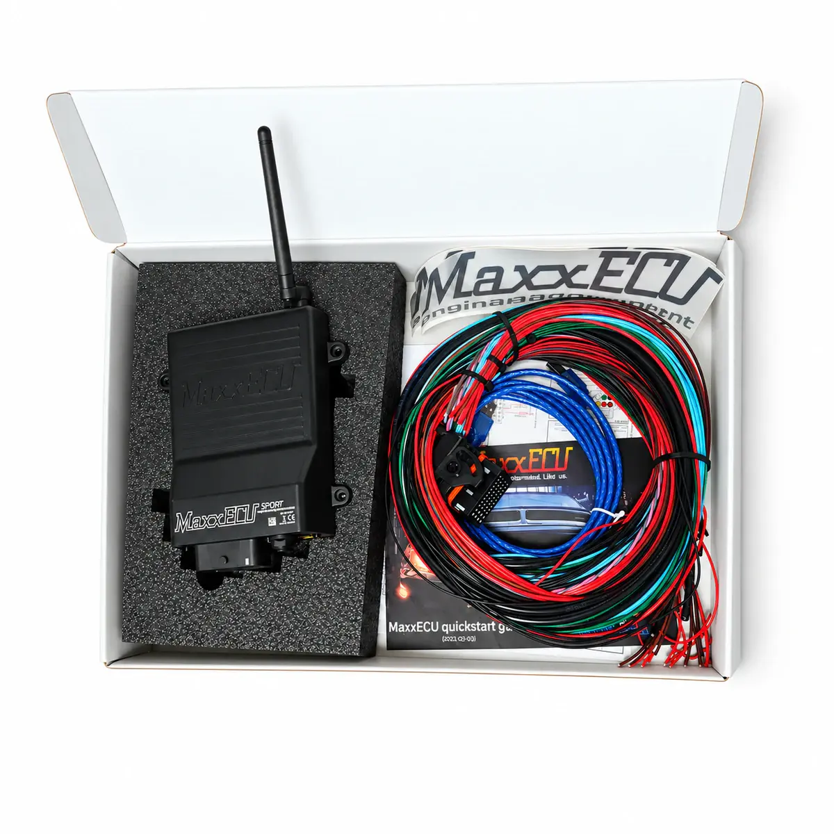
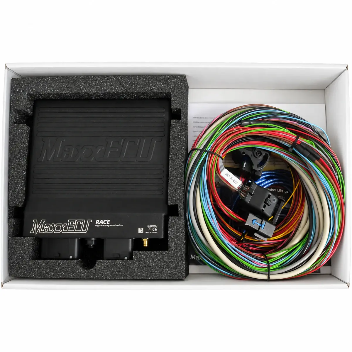
Start with the ECU, main relay, fuses and grounds. Then add pumps, coils and solenoids. Their current and driver requirements determine whether an ECU output can control them or needs a relay or power module.
Sensors and their controllers
List crank and cam triggers, pressure, temperature, position and lambda measurements. Each needs the right supply, ground, input and calibration. An LSU wideband probe also needs control electronics; it is not an analogue-output module.
Interfaces and verifiable functions
Mark which connections use loose terminals, flying leads or a finished harness. Add the PC interface, CAN devices and logging. For each function, identify its input, output driver and a way to test it.
Reference documents
- MaxxECU — GEN1 pinout, trigger system and troubleshooting
- Document language: English
- Referenced chapters: Pin allocation, trigger synchronization and output tests
- Link — G4X and G4+ Quickstart Guides / PCLink Help
- Document language: English
- Referenced chapters: Sensors, shared I/O, CAN, logging and first start