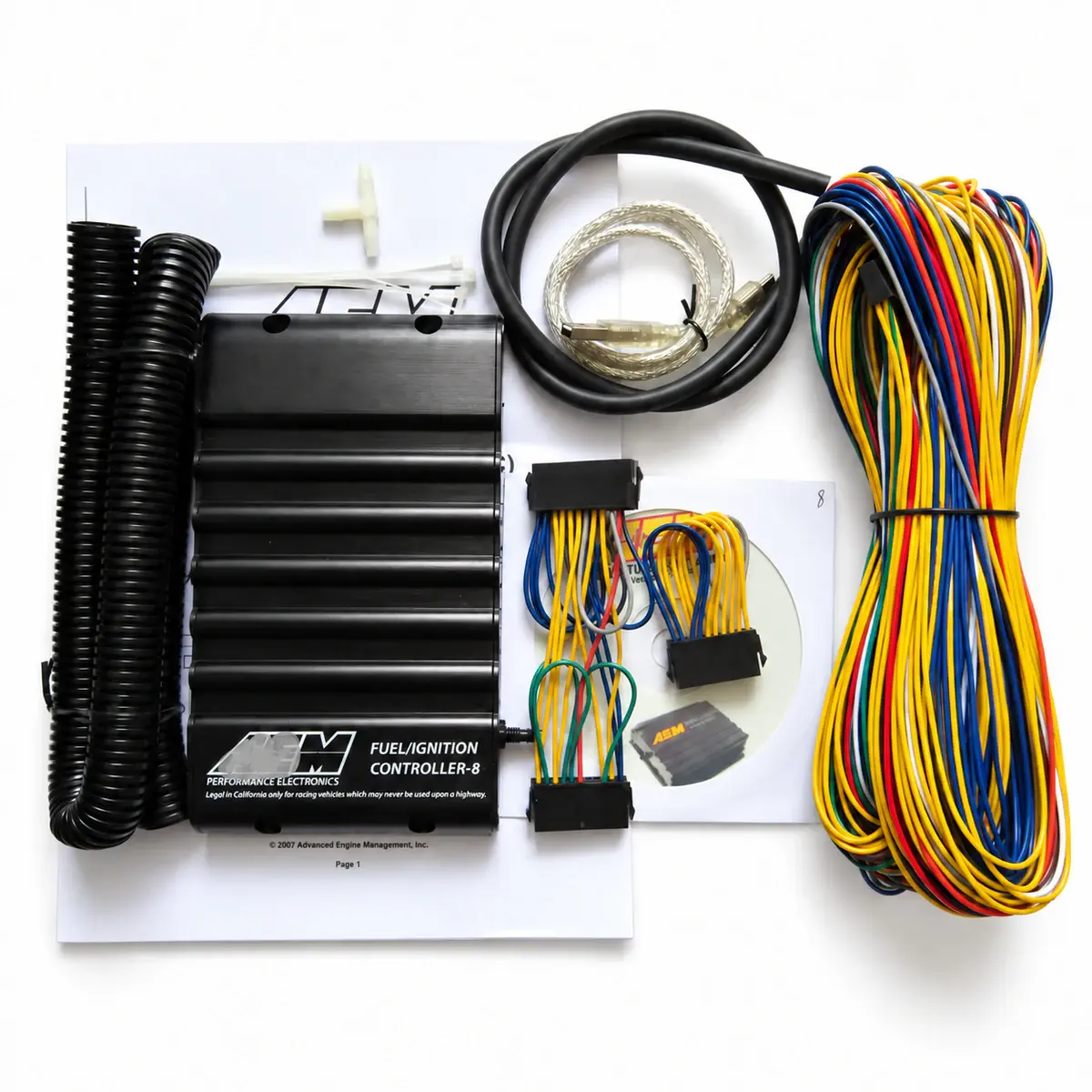
Applicability
Applies to the stated manufacturer reference model; wiring must match the actual hardware revision.
How it works with the factory ECU
F/IC8 modifies signals while the factory ECU remains active. It intercepts injector pulse widths and selected input signals. Ignition correction retards timing; this is neither a standalone ignition ECU nor a timing-advance device.
Channels and electrical limits
Treat operating range, driver limits and measurement range separately. SW12 is a current-limited high-side output, not a general supply for arbitrary accessories.
| Item | Specification / revision condition |
|---|---|
| Model / part number | 30-1930 |
| Injector outputs | 8 intercepted injector channels |
| Calibration tables | 8 configurable maps, 21 × 17 cells |
| Fuel correction | Increase or decrease the factory injector pulse width |
| Ignition correction | Retard only; load from MAP, MAF or TPS |
| Manifold pressure | Internal MAP used as an absolute-pressure load input |
| Electrical signal | MAF, analogue A/B and O2 correction maps |
| Software / communication | AEM F/IC software / USB driver |
| Auxiliary outputs | PWM boost-solenoid output; frequency-based MAF correction |
| Operating supply | 8–15 V DC |
| Internal logging memory | 2 MB |
| Internal logging interval | 10–1275 ms; fastest interval is 100 samples/s |
| Internal MAP range | 2–40 psia absolute; accuracy ±0.5 psia, resolution 0.1 psia |
| MAF / analogue voltage range | 0–6 V input and output; overload protected |
| Injector driver current limit | Driver current limit 1.7 A, with overload protection |
| Switched 12 V output | High-side driver, 1 A maximum |
| Calibration switching | Two calibrations, selected by the user-switch input |
| O2 correction voltage range | 0–3.5 V |
Signal taps versus intercepted circuits
A tap reads the existing signal in parallel; interception connects source and factory-ECU sides separately. Check injector, crank, cam, MAF and O2 signal direction; the two methods are not interchangeable.
Load axes and calibration tables
The internal MAP uses absolute pressure, 2–40 psia, not 40 psi of gauge boost. F/IC8 fuel, ignition and analogue tables have separate jobs; editing one table does not resolve the factory ECU’s closed-loop fuel correction.
Logging, verification and model differences
On-board logging is 2 MB with 10–1275 ms intervals; 10 ms equals 100 samples/s. SW12 is limited to 1 A, and the O2 correction range is 0–3.5 V. Do not substitute the other F/IC model’s limits. Log factory behaviour alongside piggyback corrections.
Reference documents
- AEM F/IC8 — Installation Instructions 30-1930
- Document language: English
- Referenced chapters: Channel allocation, auxiliary outputs, logging and specifications