
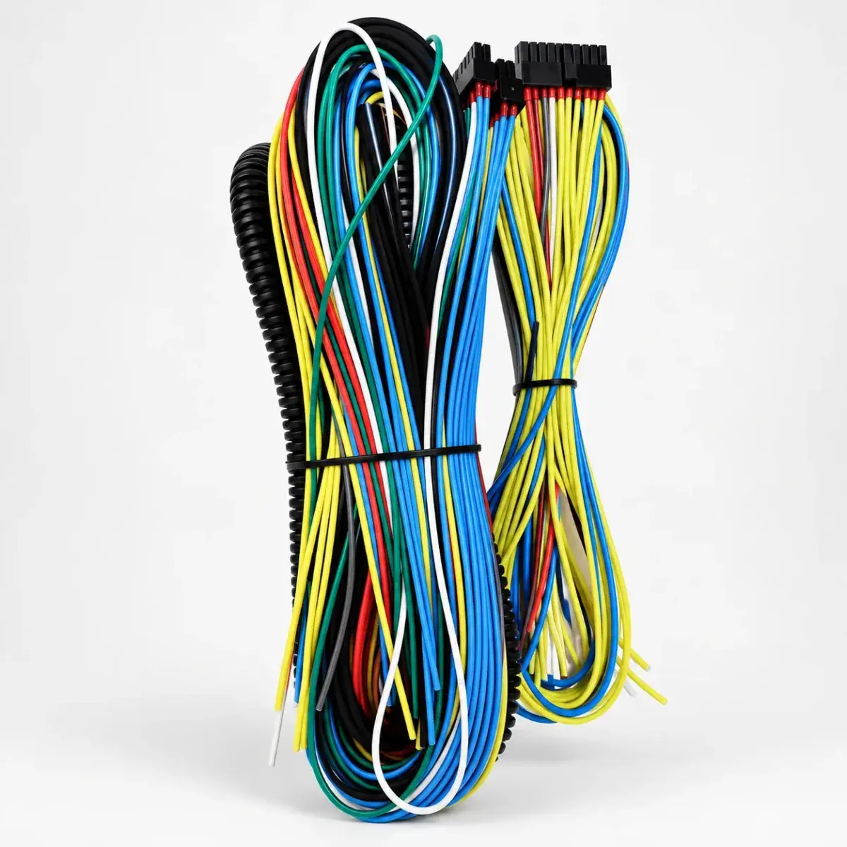
 Main harness
FIC8 Harness
$57.09–63.11
FIC8 main harness for connecting the corresponding controller to the engine management system. Termination type and supplied items are confirmed in the quote.
Controller
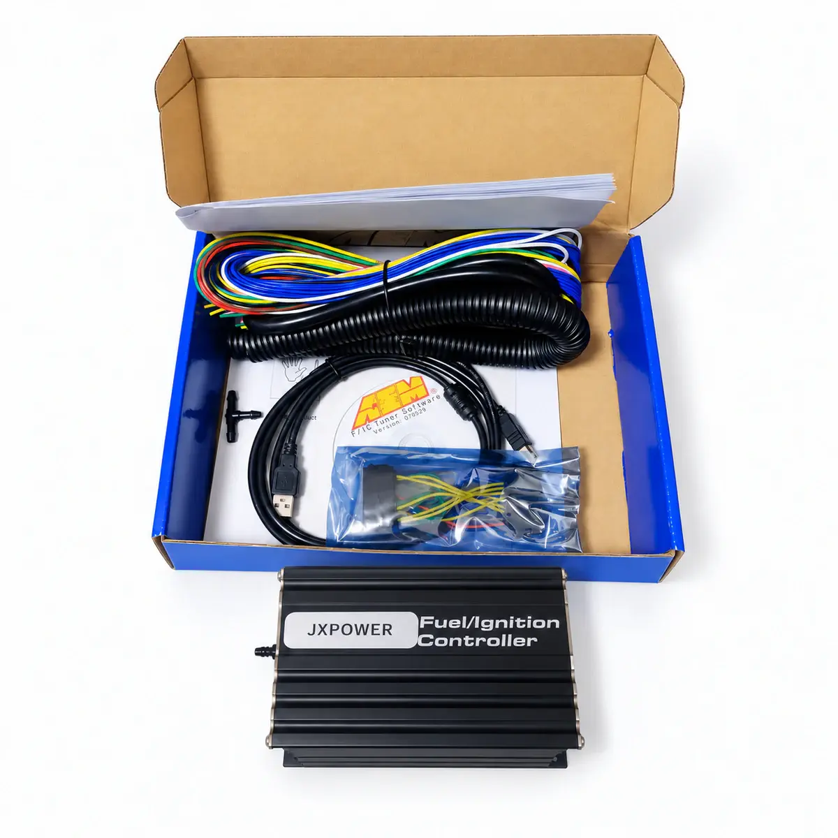
Eight-channel piggyback controller that retains the factory ECU and supports fuel correction, ignition retard and boost valve control.
Reference prices vary with exchange rates and the supplied package. Contact customer service to confirm the price, shipping and taxes.
01 / About FIC8
F/IC8 works alongside the factory ECU, intercepting 8 injector signals and correcting selected sensor signals. Its ignition table retards timing; it does not advance timing or provide standalone ignition control.
Eight intercepted injector channels retain the factory ECU.
Eight 21 × 17 maps include PWM and frequency functions.
Internal 2 MB logging supports recording without a PC.
Ignition correction retards timing; it does not advance it.
02 / Specifications
03 / Package contents
The actual supplied contents are confirmed in the itemized quote. Check the following items before payment.
Ask whether the FIC8 loom, USB cable, pressure hose and boost solenoid are supplied. The PWM output does not include a solenoid.
04 / Fitment & installation: AEM FIC8 Controller
Check the model, hardware revision and connector pins against the device’s wiring diagram.
Use the exact ECU wiring diagram; verify every circuit for continuity and shorts before connecting power.
Keep the factory ECU connected. Check the eight injector input / output pairs and crank / cam signal polarity. Allocate the frequency channel to either MAF or speedometer correction before wiring it.
Connect the internal MAP hose after the throttle body and check for leaks. Wire the boost solenoid to its assigned PWM output and verify the valve’s current requirement and hose routing.
05 / Questions about FIC8
No. F/IC ignition tables accept negative correction to retard timing, not advance it.
The universal flying-lead loom requires vehicle-specific wiring. A matching patch harness and bypass plug are separate package checks.
No. The frequency channel supports either frequency-based MAF correction or speedometer correction; these functions share the channel and cannot operate simultaneously.
F/IC8 provides boost-solenoid PWM control and needs a matching valve, wiring and plumbing. Confirm whether the valve is included in the order.
FIC8 is a piggyback controller with eight injector interception channels. It retains the factory ECU; channel count alone does not establish engine compatibility or independent control of every engine function.
Do not assume cross-model calibration compatibility. FIC6 and FIC8 have different channels and features; use the file format, software and base calibration intended for the actual controller and engine.
Yes. Internal logging has 2 MB of memory and 10–1275 ms intervals. Logging starts when the configured trigger and user-switch conditions are met; download the result through F/IC software.
Check the logging conditions in FIC Logger and whether the user-switch input is grounded. When that switch is assigned to dual calibrations, the logger trigger remains enabled; logging still waits for the configured conditions.
Changing the user switch while connected interrupts F/IC communication. Select the A / B calibration first, then connect, edit or upload the matching map.
The factory ECU continues closed-loop fuel correction and may counteract FIC8 adjustments. Compare OBD fuel trims with measured lambda, then check how the injector and O2 correction tables interact with the factory control strategy.
No. psia is absolute pressure, including atmospheric pressure. The 2–40 psia range is about 0.14–2.76 bar absolute; subtract local atmospheric pressure to obtain gauge boost.
No. F/IC6 SW12 high-side output is limited to 6 A; F/IC8 is limited to 1 A. Use each model’s limits and pinout; injector-driver limits are separate.
No. Tap circuits read signals in parallel; intercept circuits require separate input and output connections after cutting the original circuit. Check direction, trigger polarity, continuity and shorts for each circuit.
06 / Manuals & resources
EXPLORE / Related products
Main harnessFIC8 main harness for connecting the corresponding controller to the engine management system. Termination type and supplied items are confirmed in the quote.
 Controller
FIC6 piggyback controller for tuning projects that retain the factory ECU.
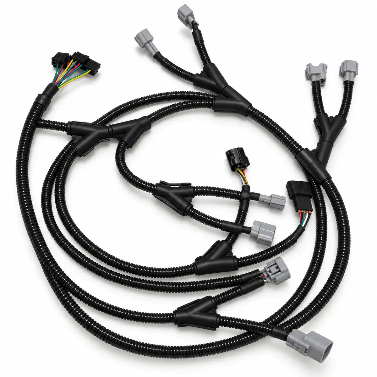 Vehicle adapter
Prado FIC6 adapter harness for matching factory Prado wiring to a piggyback controller.