Applicability
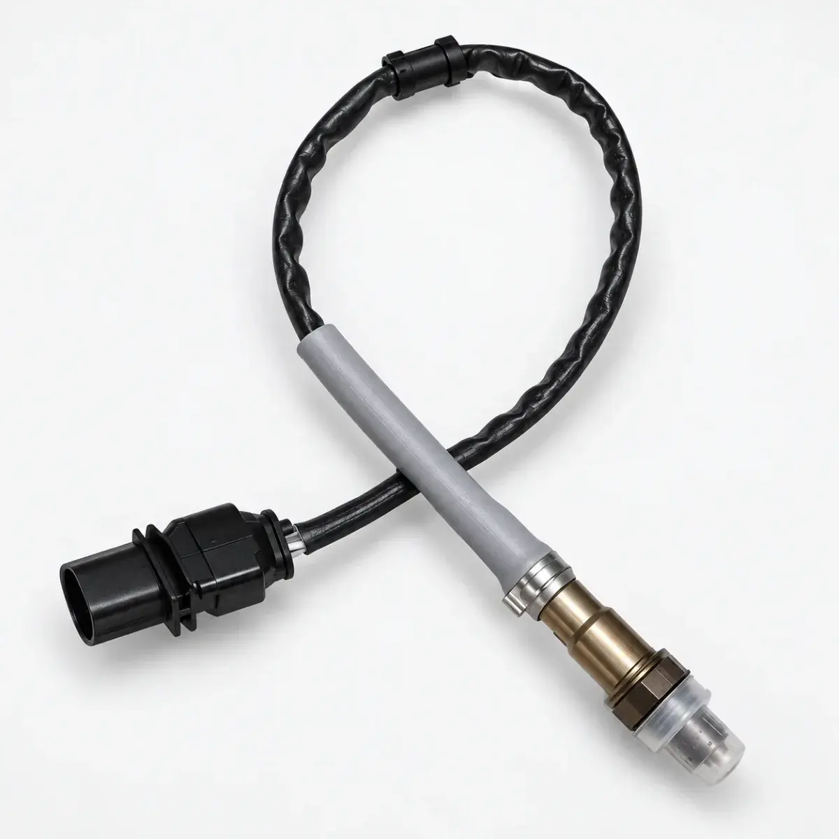
Bosch Motorsport LSU 4.9 reference; not a generic calibration for every wideband sensor.
Why an ordinary analogue input is insufficient
LSU 4.9 needs a dedicated control circuit for the pump cell and heater. UA in the data sheet is an evaluation-circuit output, not a direct sensor voltage. Use the matching controller’s CAN / analogue signal, or an ECU interface explicitly supporting LSU 4.9.
Measurement and installation limits
Range and temperature constraints are separate; exhaust temperature alone does not establish a suitable installation point.
| Item | Value |
|---|---|
| Measurement range | λ 0.65–∞ |
| Thread | M18 × 1.5 |
| Continuous exhaust temperature | < 930 °C |
| Short-term exhaust temperature | < 1030 °C |
| Hexagon temperature | < 600 °C |
| Connector temperature | < 140 °C |
Placement, condensation and leaks
Choose a representative exhaust location within all component temperature limits. Where possible orient the cable upward and protect against condensation. Avoid the tailpipe outlet and check upstream leaks that may distort readings.
Connector signals and trim resistor
The six functions cover pump current, virtual ground, heater terminals, trim resistor and Nernst voltage. The factory connector’s trim resistor belongs to the measurement system; do not treat it as a replaceable ordinary wire junction. Verify pin viewing direction for the exact connector.
Reference documents
- Bosch Motorsport — Lambda Sensor LSU 4.9 data sheet
- Document language: English
- Referenced chapters: Technical Specifications, Connectors and Wires, Installation Notes